Available fault current and source cases
Maximum and minimum source conditions should be evaluated where applicable. Lower available fault current can produce higher when the resulting arcing current falls into a slower trip region.
Arc flash studies use short-circuit and coordination model data, along with additional equipment parameters to calculate and for equipment that may be examined, adjusted, serviced, or maintained while energized.
An arcing fault can occur between phase conductors, from phase to neutral, or from phase to ground when air becomes an ionized conductive path. Unlike a bolted fault, the arc has impedance, produces intense heat and light, and can continue until a protective device clears the fault or the arc can no longer sustain.
During an arc flash event, electrical energy is released through the arc in the form of heat, light, molten metal, vaporized conductor material, sound, and rapidly expanding gases. The arc flash portion generally refers to the thermal energy exposure that can cause burns and ignite clothing. The arc blast portion refers to the pressure wave and mechanical effects that may accompany the arc, including sound pressure, shrapnel, flying molten metal, and force from rapidly expanding vaporized metal and gases.
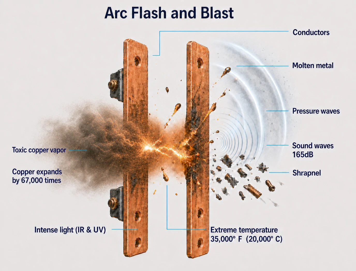
An arc flash hazard study uses the short-circuit and coordination model, along with equipment-specific inputs, to calculate arcing current, protective device clearing time, , and . These calculations primarily quantify thermal exposure. Blast-related effects may also occur during an arc flash event, but they are not fully represented by the value. For this reason, calculated should be understood as one part of the overall hazard associated with energized equipment work.
Maximum and minimum source conditions should be evaluated where applicable. Lower available fault current can produce higher when the resulting arcing current falls into a slower trip region.
Arc flash calculations account for equipment type, voltage, electrode or bus configuration, enclosure dimensions, conductor gap, , and calculated bolted fault current.
is strongly affected by protective device clearing time at the calculated arcing current. Relay, fuse, and breaker characteristics, adjustable settings, maintenance modes, , and control schemes may affect the evaluation.
The highest hazard may occur on the line side of a main breaker or in equipment sections not isolated by the main device. In those cases, the applicable upstream protective device is used to determine clearing time.
NFPA 70E addresses electrical safety-related work practices, including energized work planning, shock and arc flash risk assessments, selection, training, and electrical safety program responsibilities. The NEC addresses installation and marking requirements, including arc flash hazard warnings for applicable equipment. The adopted edition and AHJ requirements should be verified for each project location.
Power System Calcs provides the calculated , , and label information as part of the study. This information is intended to support the facility's electrical safety program, which remains the responsibility of the facility owner or operator.
IEEE 1584-2018 is used for three-phase AC equipment from 208 V through 15 kV where the equipment and input data are within the method's applicable range. The calculation considers available fault current, arcing current, protective device clearing time, electrode configuration, enclosure dimensions, conductor gap, , and related equipment parameters to determine and .
For equipment outside the scope of IEEE 1584, such as many applications above 15 kV or certain utility distribution configurations, other defensible methods may be used where appropriate. These may include the Lee method, ArcPro-based analysis, NESC-based approaches, or EPRI/Short-Eblen research-based methods. The selected method, assumptions, and limitations should be documented.
Use the short circuit study to confirm that equipment interrupting and withstand ratings are adequate for the calculated available fault current. Arc flash labels should not be used as a substitute for correcting improperly rated equipment.
Assign arc flash model parameters such as equipment type, enclosure size, conductor gap, electrode configuration, and using available project data, typical configurations, and conservative assumptions.
Evaluate applicable source lineups, generator cases, tie configurations, maintenance modes, and maximum/minimum fault contribution cases.
Review calculated and results, resolve anomalies, document assumptions, and prepare labels after the model and inputs are validated.
After initial arc flash runs, an arc flash mitigation review can determine whether protective device settings can be reduced during energized work without sacrificing normal coordination. Additionally, energy-reducing maintenance switches, , , optical detection, or other arc flash mitigation systems can be considered.
Mitigation should be evaluated carefully because lowering settings may improve arc flash performance while changing selective coordination or sensitivity to inrush currents or other normal transients. The applicable zone of protection should also be confirmed, since some mitigation schemes may reduce the hazard for bus or load-side faults but may not reduce for an arc fault on the incoming line side of the main breaker.
NFPA 70E recognizes both the arc flash category method and the analysis method. Power System Calcs uses the analysis method and generally recommends labels based on levels or energy bands. Labels based on specifically calculated results can also be provided where preferred by the facility owner.
may then be selected by the facility using NFPA 70E procedures, the calculated , the , or the level shown on the label.