Relay-based devices
Protective relays often show trip time only. Breaker clearing time, relay output time, auxiliary devices, and CT accuracy must be considered separately.
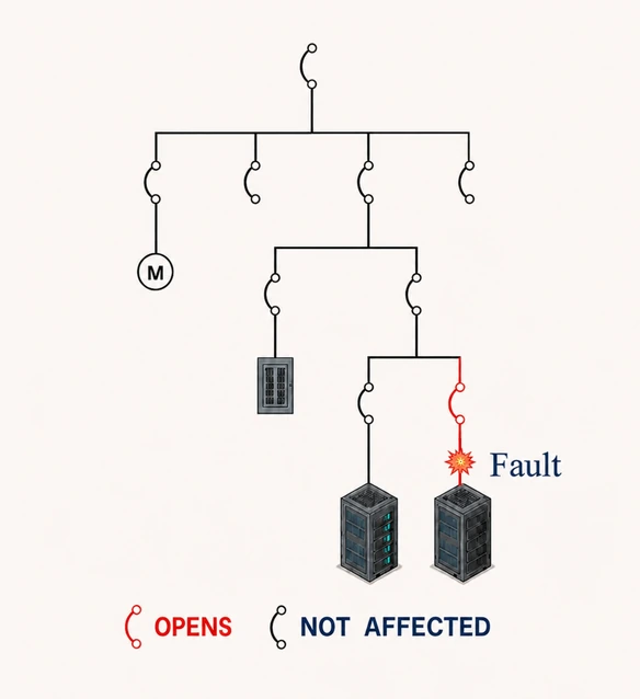
Coordination studies evaluate breakers, relays, fuses, and other protective devices to determine if the device closest to the fault clears first. When practical, settings are adjusted to improve coordination while still protecting conductors, transformers, generators, motors, and other equipment.
Coordination is the time-current relationship between protective devices that determines which device operates first for a fault or abnormal condition. Proper coordination allows the protective device nearest the fault to clear the condition while upstream devices remain closed where practical, limiting the outage to the affected portion of the system.
A coordination study evaluates protective device characteristics and selects settings intended to achieve that behavior while balancing fault isolation, equipment protection, and continuity of service.
Settings should not be so high that equipment is exposed to damaging currents, or so low that normal transients, transformer inrush, motor starting, or acceptable operating conditions cause nuisance trips.
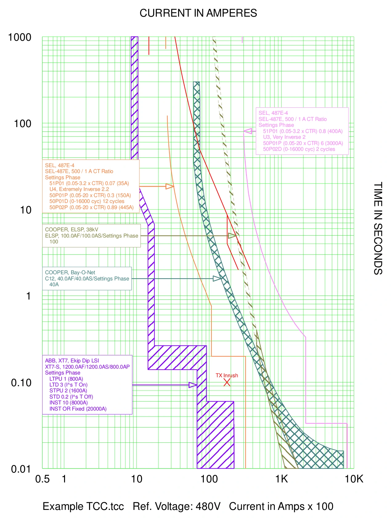
A time-current characteristic curve (TCC) plots current on the horizontal axis and time on the vertical axis, typically using logarithmic scales. By overlaying downstream and upstream protective devices, the study can evaluate whether the downstream device clears first and whether adequate separation exists between device curves.
TCCs are also used to compare protective device settings against transformer inrush, motor starting, cable and transformer damage curves, and generator decrement curves. The curves are evaluated up to the available fault current calculated in the short circuit study.
Protective relays often show trip time only. Breaker clearing time, relay output time, auxiliary devices, and CT accuracy must be considered separately.
Published low-voltage breaker TCCs commonly show total clearing time, so the curve already includes the breaker clearing behavior represented by the manufacturer.
Legacy IEEE 242 Buff Book guidance includes reasonable CTI allowances between combinations such as breakers, relays, and fuses, including tolerances and breaker operating time.
Coordination in the instantaneous region can be difficult to achieve. Selectivity may depend on device type, manufacturer data, , , or tested combinations.
The study checks whether protective devices clear faults fast enough to protect equipment damage curves while still allowing expected transient events to ride through. Transformer inrush, motor acceleration, generator decrement, cable withstand, and transformer through-fault limits can all shape the final settings.
Where code-required selective coordination applies, such as emergency systems, legally required standby systems, critical operations power systems, fire pumps, and other specific systems, the study should clearly document any cases where the required level of coordination could not be achieved.
If equipment is identified that may not comply with protective device related NEC requirements, the condition should be communicated to site personnel. Examples include missing or inadequate ground-fault protection of equipment for qualifying 1000 A or larger disconnects on solidly grounded wye systems, or missing arc-energy reduction provisions for circuit breakers with a highest continuous current trip setting of 1200 A or higher.
Gather protective device manufacturer, model number, frame, trip unit, sensor, fuse class, relay model, CT ratios, and existing settings where applicable.
Create TCCs for each meaningful source-to-load path, including utility, generator, tie, bypass, and maintenance configurations where applicable.
Adjust long-time, short-time, instantaneous, and ground-fault, or time overcurrent/definite time responses including time delays, to balance coordination and protection.
Provide setting tables so commissioning agents and testing technicians can set devices exactly as intended. Review as-left relay settings files to ensure relay settings match the recommended settings.
Incident energy depends heavily on protective device clearing time at the calculated arcing fault current. For this reason, the coordination study should be completed before final arc flash calculations and labels are developed.
The coordination study develops protective device settings with arc flash performance in mind. However, arc flash mitigation through reduced or modified settings requires an additional review of the settings. This add-on service, if requested by the Client, is performed after the initial coordination settings are established and the preliminary arc flash results are available. The evaluation identifies locations where incident energy may be reduced through settings adjustments while maintaining appropriate coordination and equipment protection.